Cyclic Salt Spray Chamber
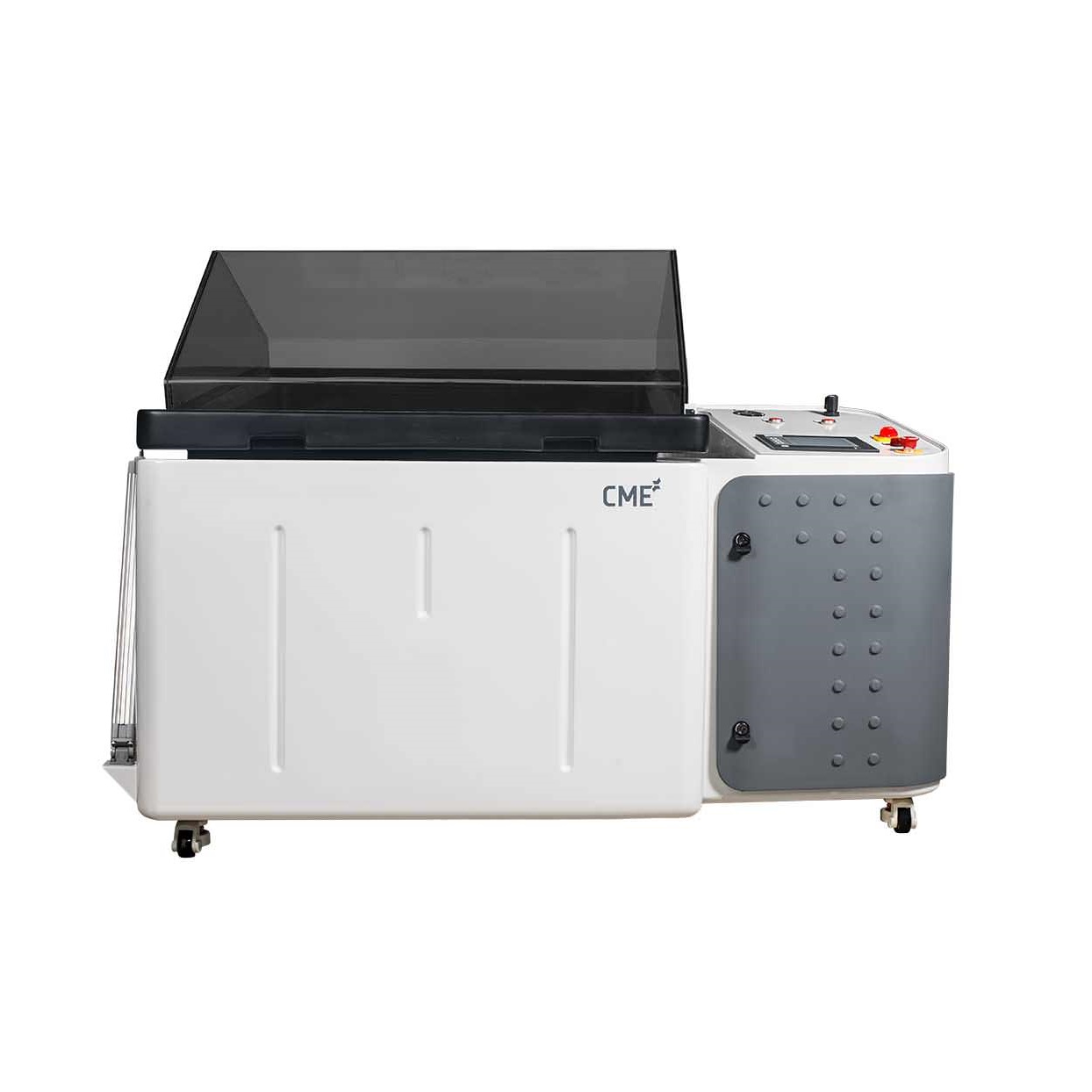
Recent years have demonstrated that cyclic salt spray chambers provide a more realistic simulation of real-world corrosive environments compared to the traditional salt spray testing method. The salt spray test operates at a single temperature set point (ambient to 55°C) in continuous mode. This makes the cyclic corrosion test more reliable for evaluating corrosion resistance.
Recent years have demonstrated that cyclic salt spray chambers provide a more realistic simulation of real-world corrosive environments compared to the traditional salt spray testing method. The salt spray test operates at a single temperature set point (ambient to 55°C) in continuous mode. This makes the cyclic corrosion test more reliable for evaluating corrosion resistance.
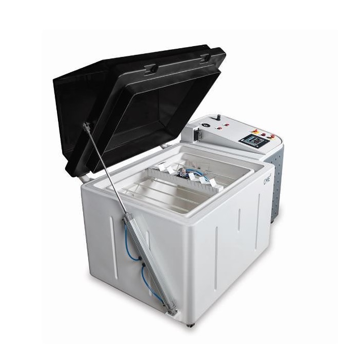
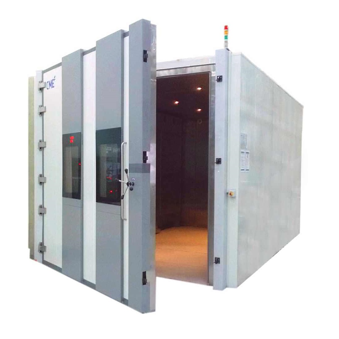
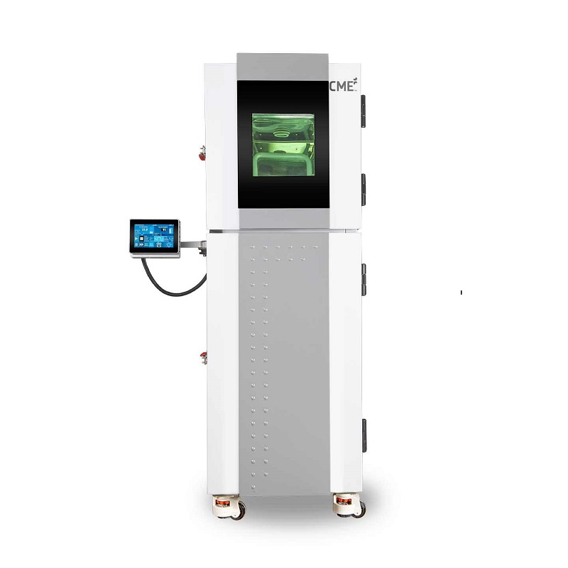
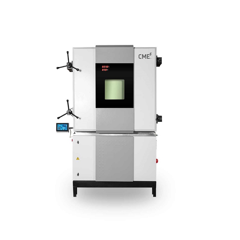
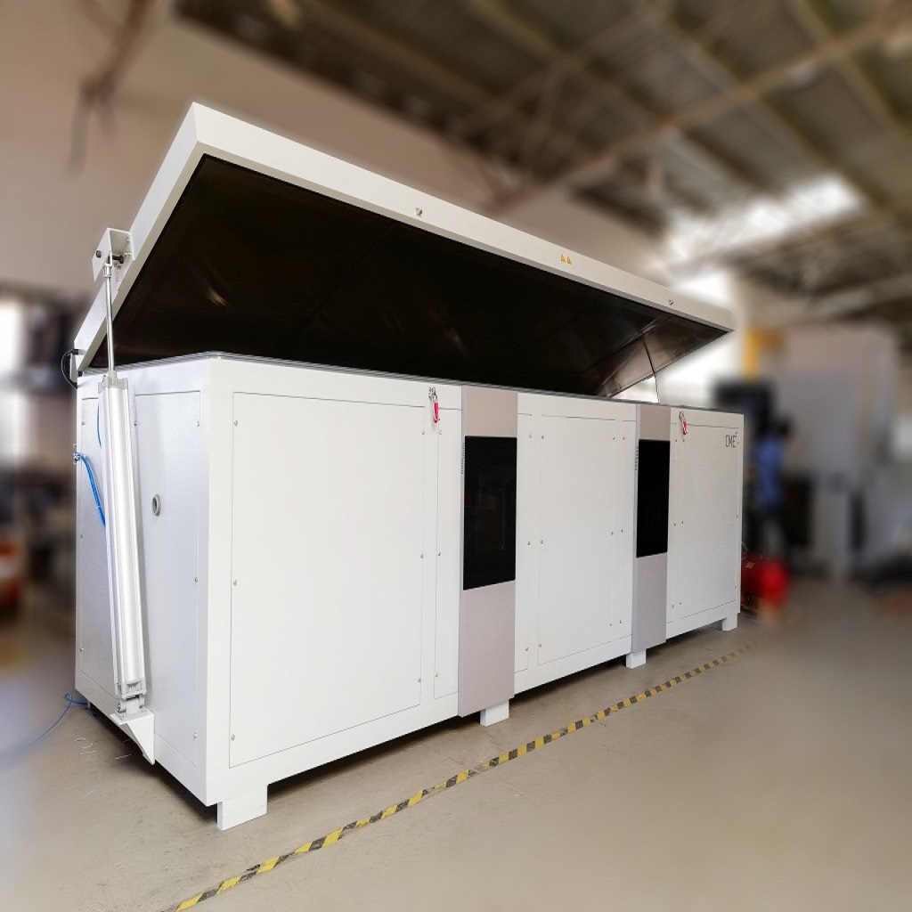
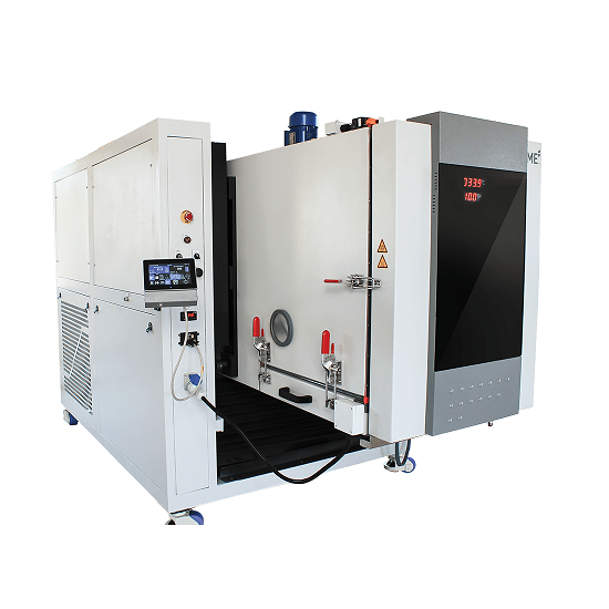
CME cyclic salt spray chambers are designed to be highly flexible, accommodating a wide range of CCT specifications. These chambers can be programmed to conduct various corrosion tests, including wet cycle, dry cycle, controlled humidity, and the salt spray test, all within a single chamber. The sequence of tests can be customized and repeated automatically. Optional accessories are available to add additional climates, expanding the range of climates and conditions that can be simulated.
Corrosion testing involves adherence to multiple test standards established by automobile manufacturers or specific country standards. To accommodate this diversity, CME has engineered both its SF-CCT and SF-SST chambers to comply with over 100 global test standards, including ASTM, MIL, ISO, JASO, GM, NFX, AS, ECC, and more.
Got Technical Question!
| Model Selection table | ||||||||||
| Specification | ||||||||||
| Units | SF-450-SST | SF-450-CCT | SF-1000-SST | SF-1000-CCT | ||||||
| Test Space Dimensions with Hood (wxdxh) |
mm In |
800 x 730 x 1300 [868 Ltrs] 31.5 x 29 x 51 [ 30.6 Cuft] |
1680 x 800 x 1400 [1678 Ltrs] 66 x 31.5 x 55 [59.2Cuft] |
|||||||
| Test Space Dimensions without Hood (wxdxh) |
mm In |
850 x 730 x 820 [519 Ltrs] 33.5 x 29 x 32 [18.3 Cuft] |
1680 x 800 x 890 [951 Ltrs] 66 x 31.5 x 35 [33.6 Cuft] |
|||||||
| External Dimensions (WxDxH) |
mm In |
1720 x 1080 x 1520 68 x 42.5 x 60 |
1720 x 1370 x 1520 68 x 54 x 60 |
2538 x 1155 x 1625 100 x 46 x 64 |
2538 x 1525 x 1625 100 x 60 x 64 |
|||||
| Temperature Range | °C °F |
5 above ambient to 55 41 above ambient to 131 |
5 above ambient to 70 41 above ambient to 158 |
5 above ambient to 55 41 above ambient to 131 |
5 above ambient to 70 41 above ambient to 158 |
|||||
Ethernet
Ethernet capability to remotely monitor and control the chamber.

USB
USB Type-A host port to connect a keyboard or mouse or download CSV data via pen drive [max 2GB] USB Type-B data port for connection to PC for software upgrade and access memory card storage

Web Server
Built-in web server allows remote view or control from any internet connected PC, tablet or smart phone

NI Lab view
The communication which used is MODBUS RTU protocol, which is an international standard for communication in process instrumentation and automation. Necessary changes to be made in the user’s software to communicate this in MODBUS RTU universal protocol. This feature can be used manual mode only.

Hardware
Enhanced with modular controller integrating multi-zone PID control and data acquisition. SIMATIC programmable logic controller. Touch screen controller, PLC and other controller components are of a generic make with an OEM software. Free software upgrades up to one year.

Memory
SD card of 2GB memory will store all the test program data and also the diagnostic data. This card is accessible by USB and Ethernet.

Digital Events
1 digital output for switching test specimen via potential free contacts, load max. 24 VDC, 5A

Programs
99 independent programs can be stored with name and number. Each of these programs have segments which can be looped to a previous segment and repeated up to 999 cycles, creating almost unlimited number of segments The chamber can be operated in manual mode, where the set point can directly be changed in the home screen The ramp rate can be set as a value in °C/min or ramp time Graphical representation of the temperature program The time is logged only when the set valve is within the band.

Trend Graph
Real time trend graph for temperature set value, temperature process value, humidity set value and humidity process value. Options of zoom in/out, pan and individual plot selection

Security
Multi level security of guest, user, admin and factory level users with individual password protection All settings can be reset to factory defaults using admin login

PID
6 zone based PID’s with auto recall of PID based on type of program, segment and zone can be set. Each of these PID’s can be set by using the auto tune feature or manually based on user’s requirements.

Process Mimic
Graphical representation of the working of the chamber, with live status of all the components, including the current temperature/humidity process values, compressor suction/discharge pressures and return gas temperature

Power Resumption Modes
In case of a power failure, option of conditional restart based on temperature/time or continuous

Diagnostics
Event viewer will display a log of all errors/actions with a date and time stamp PLC inputs and outputs status will be indicated

Service Monitor
Log of critical components life cycle with a predefined life cycle time and elapsed time in hours

Delay Start
Real time clock based, delayed start function


