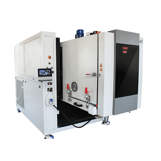
Thermal Shock Chamber
The KTS series of the thermal shock chamber meets all of the major international test standards such as MIL-883H, MIL-202G -107G, JESD22-A104D, IEC 60068-2-14, JASO D014-4, EIAJ ED-2531A and JIS C 60068-2-14.
The KTS series of the thermal shock chamber meets all of the major international test standards such as MIL-883H, MIL-202G -107G, JESD22-A104D, IEC 60068-2-14, JASO D014-4, EIAJ ED-2531A and JIS C 60068-2-14.
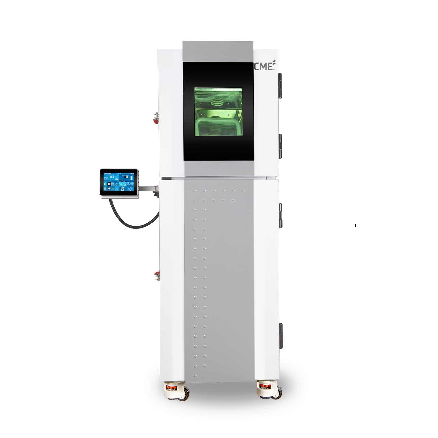
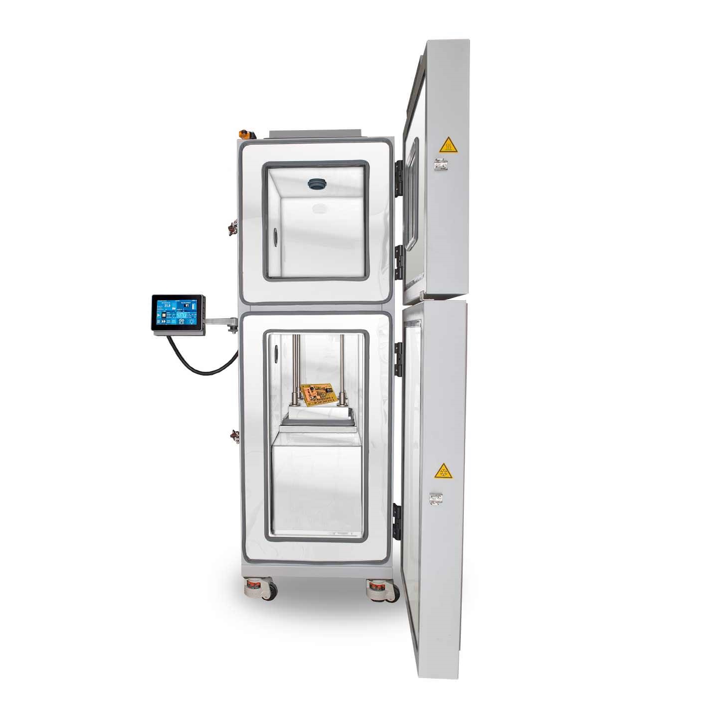
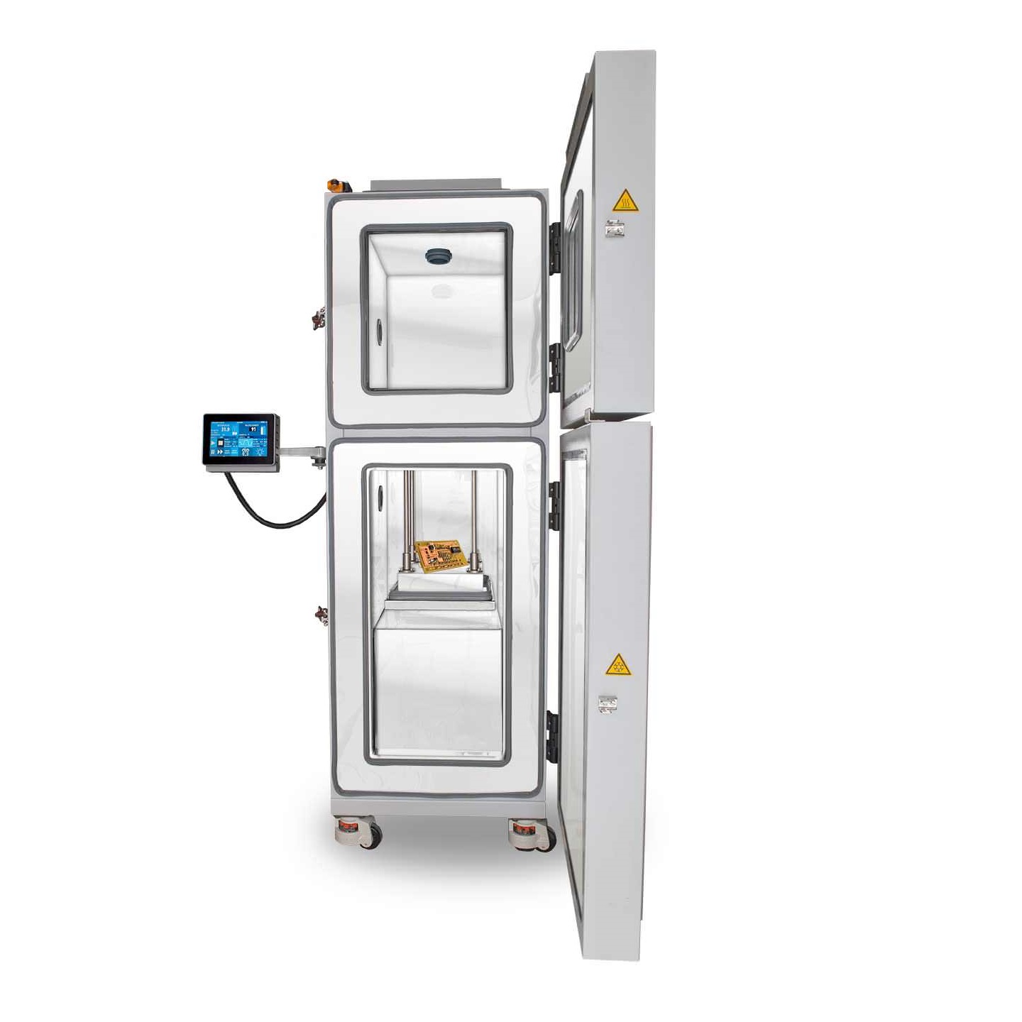
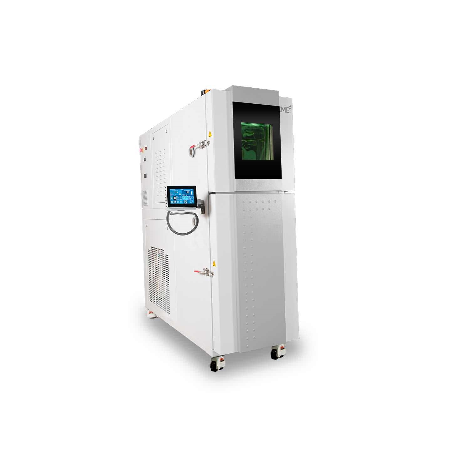
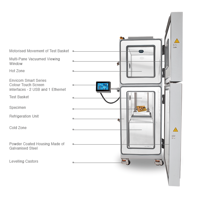
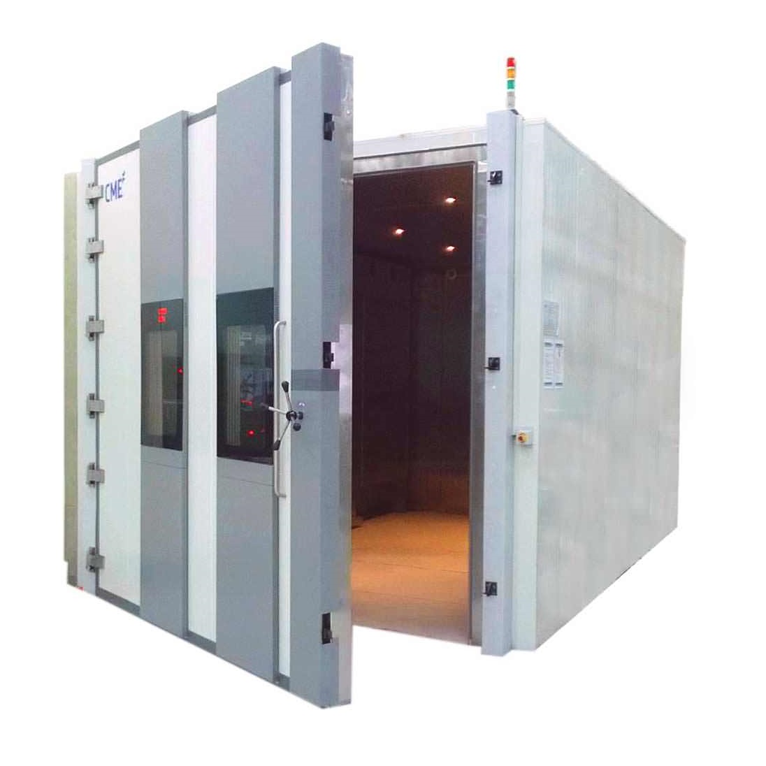
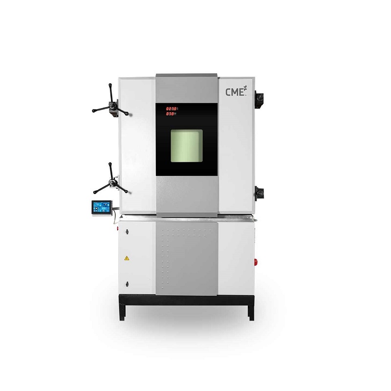
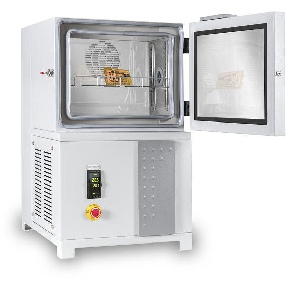
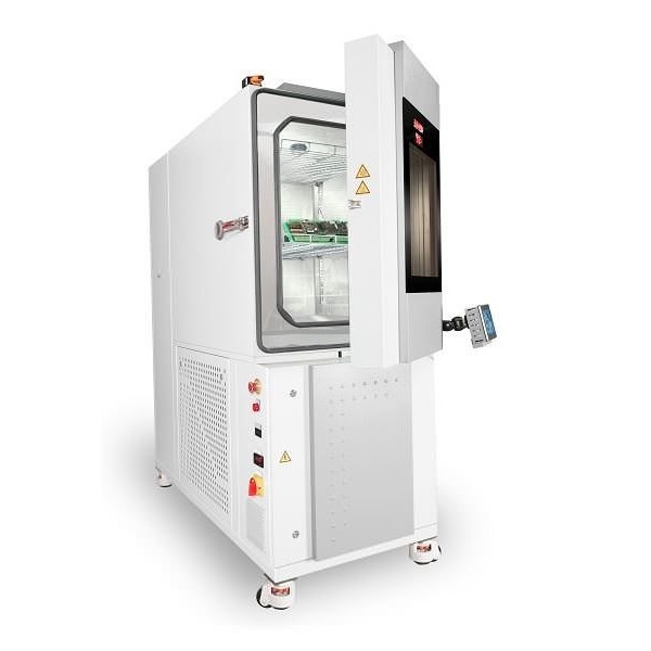
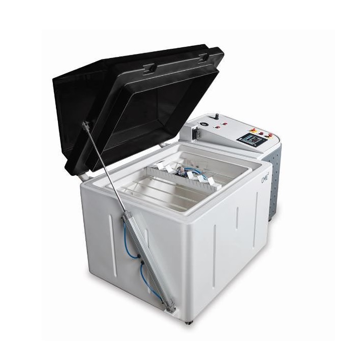
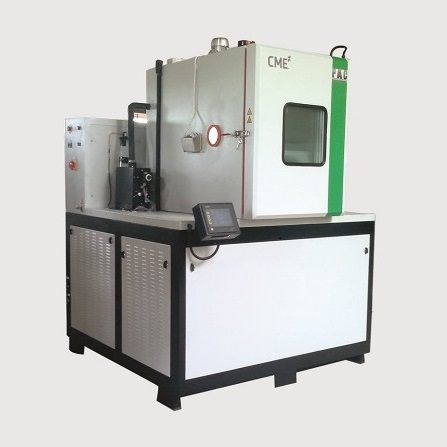
The thermal shock chamber has two zones namely the hot zone and the cold zone. The specimen is kept on the test basket, which is transferred between the hot & cold zones through a motorized system connected by a screw rod. It is primarily used to study the impact of the rapid change of temperature on the specimen. In real world scenarios, such rapid change in temperature causes cracking of the material, the mechanical failures and permanent change in electrical performance. It is therefore important to study and analyse such failures to design a better product in order to withstand such changing environmental conditions.
CME’s thermal shock chamber has recently undergone a series of technology upgrades to reduce the overall test time and to shorten the temperature recovery time while maintaining high uniformity. The result thus obtained shows consistent accuracy in temperature recovery and uniformity across multiple test cycles thereby improving the test reproducibility and reliability characteristics of the chamber. Inside the chamber, the hot and cold zones are sealed with specially designed gaskets to minimize leakage between the two zones. The Specially designed test basket of low thermal mass with a powerful temperature-conditioning unit enables the chamber to achieve faster recovery rates.
Thermal shock chamber can also be customized as per the test requirements.
Got Technical Question!
| Specification | KTS Model | ||||||||
| KTS 25-B2 | KTS 64-B2 | KTS 120-B2 | KTS 340-B2 | ||||||
| Test Basket Dimension (WXDXH) |
250 x 250 x 400 [mm] 10 x 10 x 16 [In] |
400 x400 x 400 [mm] 16 x 16 x 16 [In] |
550 x 550 x 400 [mm] 22 x 22 x 16 [In] |
700 x 700 x 700 [mm] 27.5 x 27.5 x 27.5 [In] |
|||||
| Test Basket Volume | 25 Ltr 0.9 Cuft |
64 Ltr 2.3 Cuft |
120 Ltr 4.2 Cuft |
340 Ltr 12 Cuft |
|||||
| Hot Zone Temperature Range |
50°C to + 200°C 122°F to + 392°F |
||||||||
| Cold Zone Temperature Range |
50°C to - 70°C 122°F to - 94°F |
||||||||
| Basket Transition | < 10 sec | ||||||||
| Recovery Time | < 5 min | ||||||||
Ethernet
Ethernet capability to remotely monitor and control the chamber.

Web Server
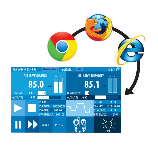
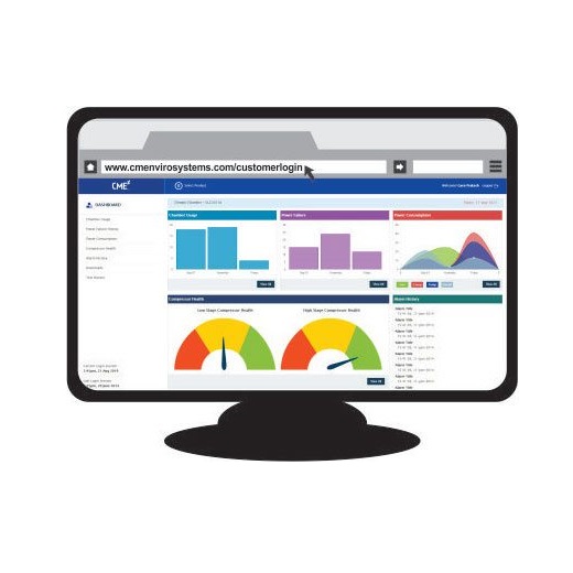
Built-in web server allows remote view or control from any internet connected PC, tablet or smart phone

USB
USB Type-A host port to connect a keyboard or mouse or download CSV data via pen drive [max 2GB] USB Type-B data port for connection to PC for software upgrade and access memory card storage

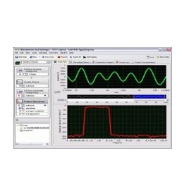
NI Lab view
The communication which used is MODBUS RTU protocol, which is an international standard for communication in process instrumentation and automation. Necessary changes to be made in the user’s software to communicate this in MODBUS RTU universal protocol. This feature can be used manual mode only.

Hardware
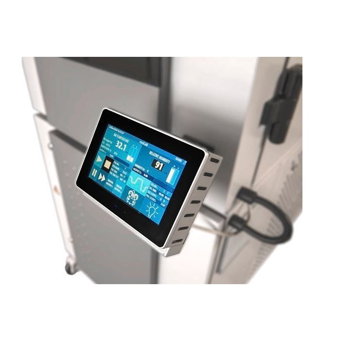
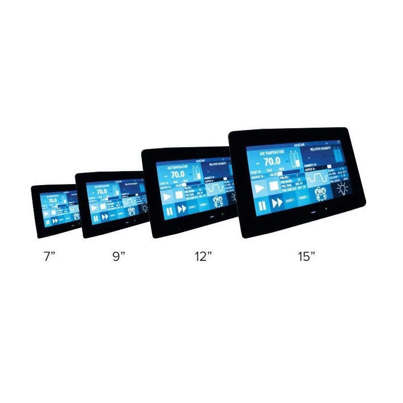
Enhanced with modular controller integrating multi-zone PID control and data acquisition. SIMATIC programmable logic controller. Touch screen controller, PLC and other controller components are of a generic make with an OEM software. Free software upgrades up to one year.

Digital Events
1 digital output for switching test specimen via potential free contacts, load max. 24 VDC, 5A

Memory
SD card of 2GB memory will store all the test program data and also the diagnostic data. This card is accessible by USB and Ethernet.

Programs
99 independent programs can be stored with name and number. Each of these programs have segments which can be looped to a previous segment and repeated up to 999 cycles, creating almost unlimited number of segments The chamber can be operated in manual mode, where the set point can directly be changed in the home screen The ramp rate can be set as a value in °C/min or ramp time Graphical representation of the temperature program The time is logged only when the set valve is within the band.

Trend Graph
Real time trend graph for temperature set value, temperature process value, humidity set value and humidity process value. Options of zoom in/out, pan and individual plot selection

Security
Multi level security of guest, user, admin and factory level users with individual password protection All settings can be reset to factory defaults using admin login

PID
6 zone based PID’s with auto recall of PID based on type of program, segment and zone can be set. Each of these PID’s can be set by using the auto tune feature or manually based on user’s requirements.

Process Mimic
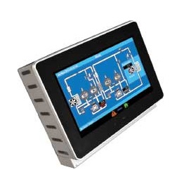
Graphical representation of the working of the chamber, with live status of all the components, including the current temperature/humidity process values, compressor suction/discharge pressures and return gas temperature

Power Resumption Modes
In case of a power failure, option of conditional restart based on temperature/time or continuous

Service Monitor
Log of critical components life cycle with a predefined life cycle time and elapsed time in hours

Delay Start
Real time clock based, delayed start function

Diagnostics
Event viewer will display a log of all errors/actions with a date and time stamp PLC inputs and outputs status will be indicated


