Executive Summary
As electric vehicle (EV) adoption accelerates globally, battery testing infrastructure has become mission-critical. Battery systems introduce thermal, electrical, and chemical risks beyond conventional environmental testing. Safe battery testing requires integrated environmental control, hazard mitigation systems, digital traceability, and scalable architecture.
This white paper presents a structured engineering framework for designing safe battery testing systems across cell, module, and pack levels.
Architectural Framework for Safe Battery Testing
CME approaches battery testing design using a layered architecture model. Each layer addresses a specific risk domain, ensuring safety, compliance, and operational reliability.
Heat Load & Thermal Management Model
Battery testing heat loads vary significantly between cell, module, and pack levels. Proper refrigeration sizing and airflow engineering must account for worst-case discharge and thermal runaway scenarios.
Hazard Mitigation Systems
Battery chambers must be designed for failure containment. Core mitigation systems include gas exhaust extraction, pressure relief panels, flame-resistant interiors, emergency shutdown logic, and integration with fire detection systems.
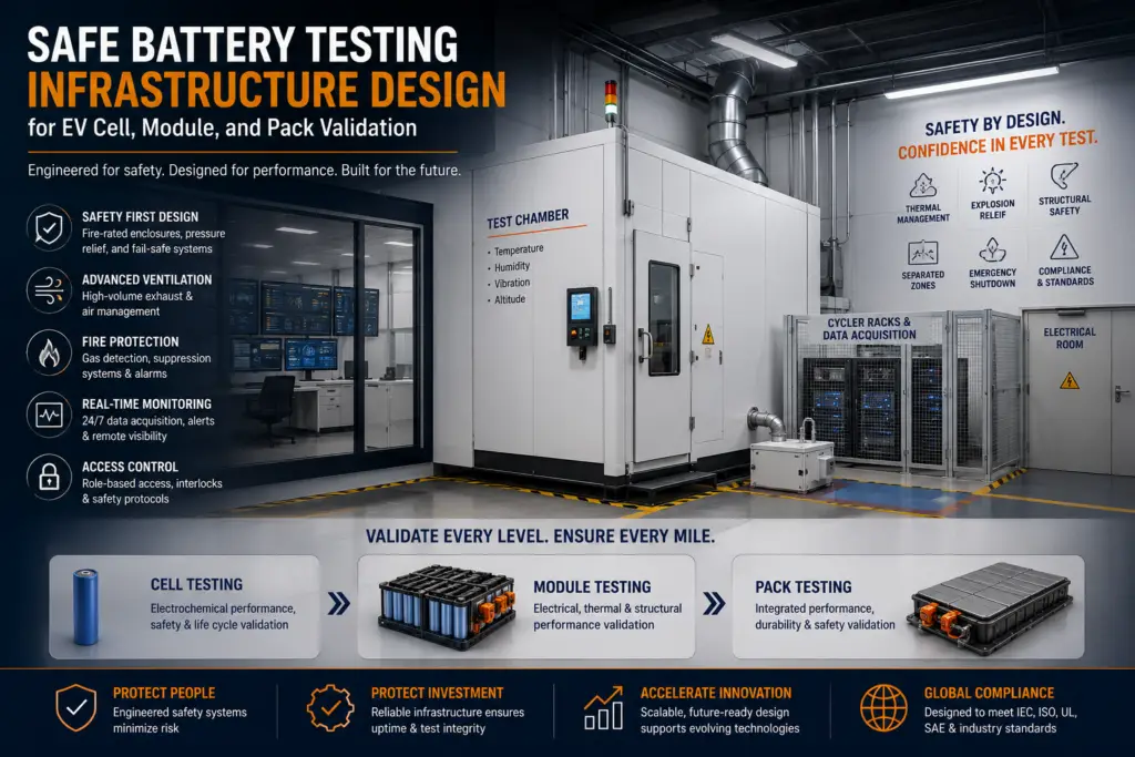
Core Elements of a Safe Battery Test Laboratory
Environmental Test Chambers
- Temperature control
- Humidity control
- Thermal cycling
- Altitude testing
- Safety interlocks
Fire Protection Systems
- Automatic suppression
- Fire-rated enclosures
- Emergency isolation
- Thermal event containment
Gas Detection
- Hydrogen monitoring
- VOC monitoring
- Electrolyte vapour detection
- Continuous monitoring
Ventilation & Exhaust
- Controlled airflow
- Emergency extraction
- Explosion venting
- Safe discharge
Electrical Safety
- Isolation
- Emergency shutdown
- Current protection
- Interlocked access
Data Acquisition
- Voltage
- Current
- Temperature
- Pressure
- Safety alarms
- Event logging
Common Risks in Battery Testing and Typical EUCAR Hazard Levels
| Column 1 | Column 2 | |
|---|---|---|
| Hazard | Typical EUCAR Hazard Level(s) | Infrastructure / Mitigation |
| Normal operation | EUCAR 0–2 | Standard environmental chamber, calibrated instrumentation, safety interlocks |
| Cell venting / Gas release | EUCAR 3–4 | Gas detection, forced ventilation, exhaust ducting, pressure monitoring |
| Thermal runaway | EUCAR 5–6 | Fire-rated chamber, thermal event containment, automatic suppression, emergency shutdown |
| Fire / Sustained combustion | EUCAR 6–7 | Fire suppression system, fire-resistant construction, emergency isolation, remote monitoring |
| Explosion / Violent rupture | EUCAR 7 | Explosion relief panels, blast protection, reinforced chamber construction, exclusion zones |
| Electrical hazards | All Levels | Safety interlocks, emergency stop circuits, insulated electrical feedthroughs, overcurrent protection |
| High temperatures | All Levels | Temperature monitoring, redundant sensors, chamber over-temperature protection, automated shutdown |
Understanding EUCAR Hazard Levels
The European Council for Automotive R&D (EUCAR) developed a seven-level hazard classification system to assess the severity of lithium-ion battery failures during abuse and qualification testing.
| EUCAR Level | Typical Event |
|---|---|
| 0 | No observable effect |
| 1 | Passive protection activated; no hazard |
| 2 | Functional damage without safety concern |
| 3 | Venting of gas or electrolyte |
| 4 | Leakage, smoke, or limited thermal effects |
| 5 | Fire or sustained thermal runaway |
| 6 | Fire with significant flame or hazardous conditions |
| 7 | Explosion or violent disassembly |
Digital Control & Data Integrity
Battery testing must incorporate programmable ramp/soak profiles, alarm logic, safety interlocks, event logging, and audit-ready data storage. CME systems powered by enviCoM™ 4.0 integrate multi-layer alarm logic and remote diagnostics via Levito digital services.
Scaling from Cell to Pack Testing
Cell testing can often be managed in reach-in chambers. Module testing introduces higher heat loads and integration complexity. Pack testing requires walk-in chambers with full safety zoning and facility-level infrastructure planning.
Conclusion
Designing safe battery testing infrastructure requires integrated environmental engineering, hazard mitigation architecture, digital traceability, and scalable planning. CME designs battery testing systems using a safety-first engineering framework that supports global EV validation programs.